
# Velocity and Pressure Drop Calculations in Water Supply Lines: CPC Section 422 Mastery for C-36 Exam
Water supply line sizing calculations form the backbone of plumbing design and are essential knowledge for C-36 exam success. Understanding velocity requirements and pressure drop calculations under CPC Section 422 ensures you can correctly size distribution piping, prevent water hammer, and maintain adequate pressure throughout building systems. This comprehensive guide breaks down the complex mathematics and code requirements you need to master.
Understanding CPC Section 422: Water Supply Velocity Requirements
CPC Section 422 provides the foundational requirements for water supply velocity in California plumbing installations. The code establishes clear parameters that every plumber must follow during design and installation phases.The Maximum Velocity Rule
The primary velocity requirement in CPC Section 422 is straightforward but critical:
Maximum velocity in water supply lines shall not exceed 8 feet per second (fps).This velocity limit applies to all pressure supply piping carrying water to fixtures and equipment. Exceeding this limit creates several problems:
- Water hammer effects - Sudden pressure surges that can damage fixtures and fittings
- Pipe noise - Audible vibrations in walls and under floors
- Erosion corrosion - Accelerated internal pipe deterioration, particularly in copper lines
- Fixture damage - Premature failure of valves, aerators, and washers
Minimum Velocity Considerations
While CPC Section 422 focuses on maximum velocity limits, codes also recognize minimum velocity concerns:
Minimum velocity should be approximately 2 feet per second to prevent sediment settlement in horizontal distribution lines. This isn't a hard code requirement in California, but industry best practice and many jurisdiction amendments include this guideline. Velocities below 2 fps allow mineral deposits and debris to accumulate in pipes, reducing flow capacity and clogging aerators.The Pressure Drop Calculation Foundation
Pressure drop—also called friction loss—represents the loss of water pressure as it travels through supply piping. Every fitting, pipe length, and elevation change contributes to total system pressure drop.
Why Pressure Drop Matters
Understanding pressure drop calculations is crucial because:
- Maintains minimum fixture pressure - Most fixtures require 20 psi minimum operating pressure
- Ensures adequate flow rates - Determines how many gallons per minute (GPM) each fixture receives
- Prevents over-pressurization - Excessive pressure damages components and wastes water
- Optimizes pipe sizing - Allows selection of economical pipe sizes that meet code
Basic Pressure Drop Formula
The fundamental relationship uses the Hazen-Williams equation, the standard method in plumbing:
hf = 0.2083 × (100/C)^1.852 × (Q^1.852 / D^4.8704) × L
- hf = Head loss (pressure drop) in feet of water
- Q = Flow rate in GPM
- D = Internal pipe diameter in inches
- L = Length of pipe in feet
- C = Hazen-Williams friction coefficient (130 for copper, 150 for PVC)
- 0.2083 = Constant for this formula with GPM input
Working with Friction Loss Tables
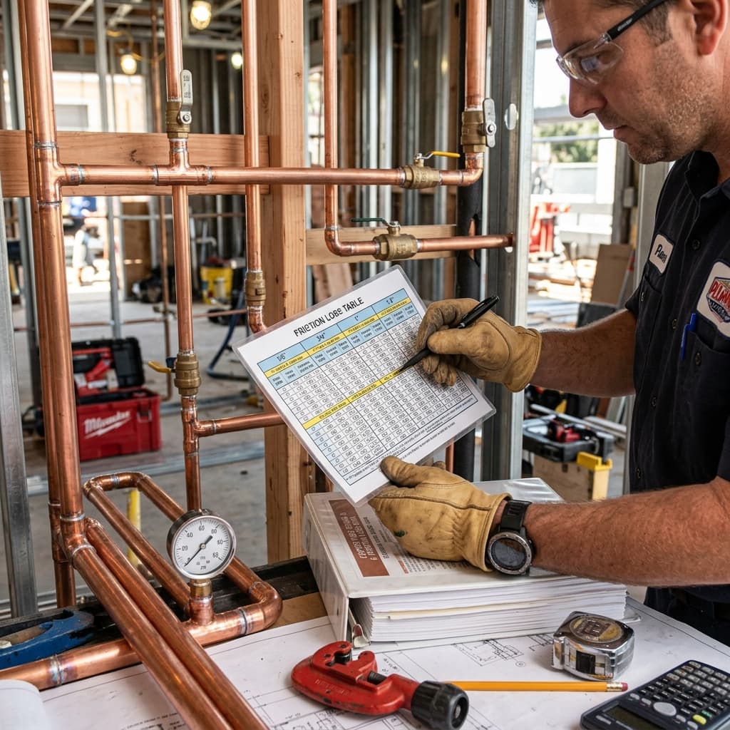
Friction loss tables simplify complex calculations and are the practical tool for exam questions and field work.
Reading Standard Friction Loss Tables
Typical friction loss tables show:
| Pipe Size | 1 GPM | 2 GPM | 3 GPM | 4 GPM | 5 GPM | |-----------|-------|-------|-------|-------|-------| | 1/2" | 21.0 | 70.0 | 145 | 245 | 368 | | 3/4" | 5.0 | 15.0 | 31 | 52 | 79 | | 1" | 1.2 | 3.5 | 7.0 | 12 | 18 | | 1.25" | 0.35 | 1.0 | 2.0 | 3.5 | 5.0 |
Table values represent pressure drop per 100 feet of pipe in psiCalculating Actual Pressure Drop
To find actual pressure drop in a specific section:
Actual Pressure Drop = (Table Value ÷ 100) × Actual Pipe Length Example:- Pipe size: 3/4"
- Flow rate: 3 GPM
- Pipe length: 50 feet
- From table: 31 psi per 100 feet
Velocity Calculations and Pipe Sizing
Proper velocity calculations determine appropriate pipe sizing to stay within CPC Section 422 limits.
Velocity Formula
Velocity (fps) = (0.408 × Q) / D²
- Q = Flow rate in GPM
- D = Internal pipe diameter in inches
- 0.408 = Conversion constant
Step-by-Step Velocity Determination
Example Problem: A water supply branch serves three fixtures with combined demand of 6 GPM. What pipe size maintains velocity under 8 fps? Testing 3/4" pipe (internal diameter ≈ 0.62"):- Velocity = (0.408 × 6) / (0.62)²
- Velocity = 2.448 / 0.3844
- Velocity = 6.37 fps ✓ (Acceptable - under 8 fps limit)
- Velocity = (0.408 × 6) / (0.50)²
- Velocity = 2.448 / 0.25
- Velocity = 9.79 fps ✗ (Exceeds 8 fps maximum)
Common C-36 Exam Calculations
Scenario 1: Sizing Main Water Supply Line
Problem: A residential building requires a main water supply line serving 200 fixture units. The water department provides 60 psi at the meter. The building requires minimum 30 psi at the highest fixture (elevation 35 feet above meter). What size copper main pipe is needed for 15 GPM demand? Solution Steps:- Calculate velocity at 15 GPM in different sizes:
- Check pressure drop for 1" copper at 15 GPM (assume 50-foot run):
- Calculate static pressure loss from elevation:
- Total pressure loss:
- Pressure at highest fixture:
Scenario 2: Riser Sizing Calculation
Problem: A 4-story residential building has a main riser serving apartments on each floor. Each floor requires 5 GPM simultaneous demand. Determine appropriate riser size and verify CPC Section 422 compliance. Solution:| Floor | Demand | Total GPM | |-------|--------|-----------| | 1st | 5 | 20 | | 2nd | 5 | 15 | | 3rd | 5 | 10 | | 4th | 5 | 5 |
Test 1" copper for main riser section (floors 1-2, demanding 20 GPM):- Velocity = (0.408 × 20) / (0.88)²
- Velocity = 8.16 / 0.7744
- Velocity = 10.5 fps ✗ EXCEEDS 8 fps LIMIT
- Velocity = (0.408 × 20) / (1.10)²
- Velocity = 8.16 / 1.21
- Velocity = 6.74 fps ✓ Acceptable
Accounting for Fitting Losses
Real-world systems include fittings that create additional pressure drop beyond straight pipe friction loss.
Equivalent Fitting Lengths
The standard approach adds "equivalent length" (EL) for fittings:
| Fitting Type | Size | Equivalent Length | |--------------|------|-------------------| | 90° Elbows | 3/4" | 2-3 feet | | 90° Elbows | 1" | 2.5-3.5 feet | | 45° Elbows | 3/4" | 1-1.5 feet | | Tees (through) | 3/4" | 2-3 feet | | Ball Valves | 3/4" | 0.5-1 foot | | Check Valves | 3/4" | 5-8 feet |
Revised Pressure Drop Calculation
Total pressure drop = Friction loss from straight pipe + Friction loss from fittingsUsing equivalent lengths, this becomes:
Total pressure drop = Table value × [(actual length + fitting EL) ÷ 100] Example: 3/4" copper line, 5 GPM, 30 feet actual pipe with two 90° elbows and one tee- Actual length: 30 feet
- Fitting equivalent length: 3 + 3 + 2.5 = 8.5 feet
- Total effective length: 38.5 feet
- From table at 5 GPM: 79 psi per 100 feet
- Actual pressure drop: (79 ÷ 100) × 38.5 = 30.4 psi
CPC Section 422 Installation Requirements
Beyond calculations, CPC Section 422 establishes specific installation standards you must understand for the exam.
Pressure Regulation
CPC Section 422.1 requires pressure regulators where water pressure from the supply exceeds 80 psi. This protects fixtures and reduces water waste. The regulator maintains downstream pressure between 50-80 psi.Support Requirements
CPC Section 422.2 mandates proper support of water supply piping to prevent stress from water hammer and vibration—directly related to velocity concerns.Accessibility Standards
All shut-off valves and pressure regulators must remain accessible per CPC Section 422.3, ensuring inspectors and technicians can verify proper operation and maintenance.Exam Tips for Mastery
Preparation Strategies
- Memorize key formula: Velocity = (0.408 × Q) / D² - this appears in multiple problem types
- Practice with tables: Get comfortable reading friction loss tables from different sources; formats vary slightly
- Understand unit conversions: Remember that 0.433 psi per foot of elevation is the standard conversion
- Draw diagrams: Sketch problem scenarios to visualize pipe runs and elevation changes
Common Mistakes to Avoid
- Confusing internal and external diameters - Tables always use internal diameter
- Forgetting fitting losses - Estimate equivalent lengths for all fittings; they add 10-30% to total loss
- Ignoring elevation changes - In multi-story buildings, elevation loss can exceed friction loss
- Exceeding velocity limits - Undersizing to save money violates CPC Section 422 and causes problems
- Misreading table values - Verify whether tables show loss per 100 feet or per foot
Quick Reference Velocity Limits
| Pipe Size | Max Safe Flow | |-----------|---------------| | 1/2" | 3 GPM | | 3/4" | 6-7 GPM | | 1" | 10-11 GPM | | 1.25" | 16-17 GPM | | 1.5" | 23-24 GPM |
These approximations help quickly identify whether a pipe size is appropriate for a given flow rate.
Practical Application for Field Success
Understanding these calculations ensures you design systems that meet CPC Section 308.1 fixture demand calculations while maintaining code compliance. Your ability to size pipes correctly directly impacts:- Water pressure at each fixture
- System efficiency and water conservation
- Noise and vibration elimination
- Long-term durability of components
Conclusion
Mastering velocity and pressure drop calculations under CPC Section 422 is essential for C-36 exam success and professional competence. The fundamental principle—maintaining 8 fps maximum velocity while ensuring adequate pressure at all fixtures—drives all water supply design decisions. Through practice with friction loss tables, velocity formulas, and elevation considerations, you'll develop the mathematical fluency needed to solve complex exam problems and design reliable water systems. Focus on understanding the underlying principles rather than memorizing numbers, and you'll confidently handle any water supply sizing question the exam presents.